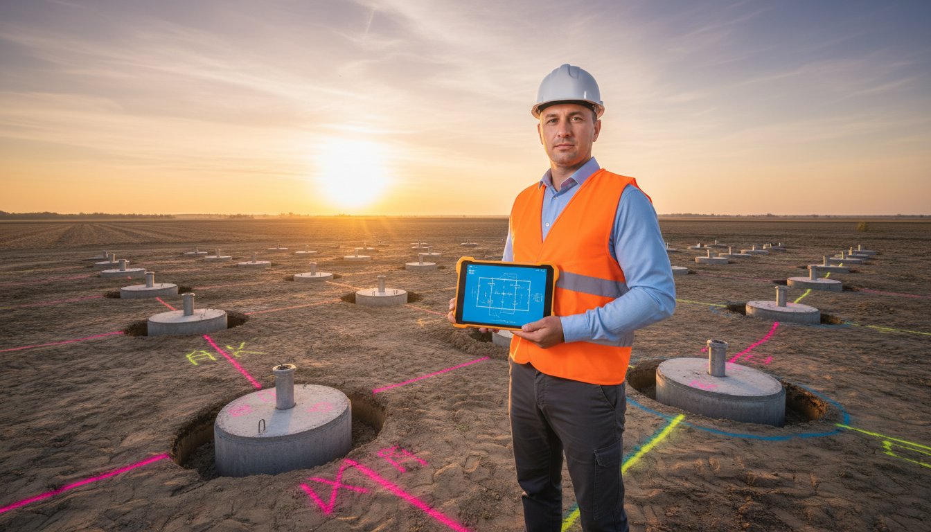
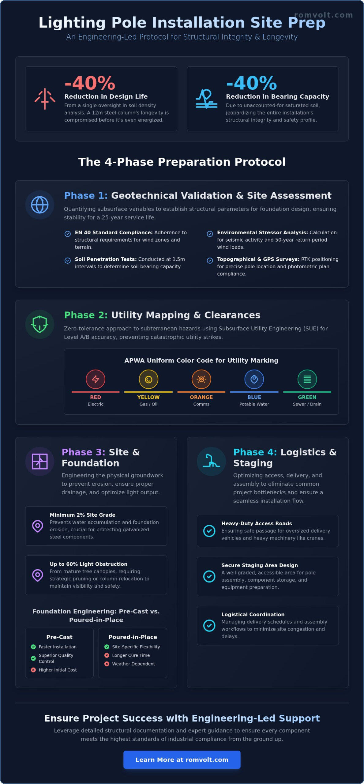
A single oversight in soil density analysis can reduce the design life of a 12-meter steel column by 40% before the first luminaire is even energized. Professional engineers understand that the success of an infrastructure project isn’t determined during the final lift, but during the weeks of rigorous planning that precede it. You’ve likely witnessed how minor inaccuracies in geotechnical reports lead to catastrophic structural shifts or utility strikes that compromise a project’s viability. Executing a flawless lighting pole installation site prep requires more than just a cleared perimeter; it demands strict adherence to EN 40 standards and absolute geotechnical precision.
This article delivers a fail-safe preparation protocol designed to ensure the structural integrity and longevity of your lighting infrastructure. You’ll master the technical requirements for subsurface utility mapping and soil compaction verification to prevent costly delays. We’ll also provide a detailed checklist for the seamless integration of pre-cast foundations and the logistics of managing oversized pole deliveries. By following this engineering-led approach, you’ll eliminate common bottlenecks and ensure your project meets the highest professional standards from the ground up.
Key Takeaways
- Understand the critical role of geotechnical validation in determining soil bearing capacity and environmental load requirements for structural longevity.
- Implement rigorous utility mapping and safety buffer protocols to prevent infrastructure damage and ensure operational safety during excavation.
- Compare the engineering specifications of pre-cast versus poured-in-place foundations to select the most efficient solution for your specific site conditions.
- Optimize logistics and assembly by mastering the technical requirements for lighting pole installation site prep, including heavy-duty access and staging area design.
- Leverage engineering-led support and detailed structural documentation to ensure every component meets the highest standards of industrial compliance.
Geotechnical Validation and Initial Site Assessment
A rigorous lighting pole installation site prep phase begins with the quantification of subsurface variables. Engineering teams must secure a comprehensive geotechnical report to establish the structural parameters required for foundation design. This process isn’t merely a formality; safety remains the primary driver to prevent catastrophic failure under peak load conditions. By evaluating the soil’s mechanical properties, we ensure the lighting column remains vertical and stable throughout its 25-year service life. Every project must align with the EN 40 standards, specifically EN 40-3-1, which dictates the structural requirements for lighting columns across various European wind zones and terrain categories.
Environmental stressors represent a significant risk factor for infrastructure. Assessment teams analyze local seismic activity data and wind load zones, often calculating for a 50-year return period to guarantee resilience. High wind speeds exert substantial lateral force on the pole’s surface area, known as the effective projected area. If the site preparation ignores these variables, the resulting foundation might lack the necessary mass or depth to counteract the overturning moment. Precision during this initial assessment phase transforms raw environmental data into actionable engineering specifications that protect the long-term investment.
Soil Analysis and Bearing Capacity
The technical team conducts standard penetration tests at intervals of 1.5 meters to evaluate soil density and composition. These tests provide the empirical data needed to determine the soil bearing capacity. Soil bearing capacity is the maximum pressure soil can support without failure or excessive settlement. When we identify high water tables, we implement specialized foundation drainage or dewatering protocols to mitigate hydrostatic pressure. Failure to account for saturated soil can lead to a 40% reduction in effective bearing capacity, compromising the entire installation’s safety profile and structural integrity.
Topographical Surveys and Grading
Engineers establish precise GPS coordinates for each pole location using Real-Time Kinematic positioning to ensure uniform light distribution according to the photometric plan. This precision prevents dark spots and ensures compliance with municipal lighting ordinances. The staging area requires grading to a minimum 2% slope to prevent water accumulation near the base of the poles. Standing water facilitates foundation erosion and accelerates the corrosion of galvanized steel or aluminum components. We also evaluate existing vegetation; a mature tree canopy can increase wind turbulence or obstruct up to 60% of the intended light output, necessitating strategic pruning or relocation of the column during the lighting pole installation site prep phase to maintain visibility and safety.
Utility Mapping and Environmental Clearances
Effective lighting pole installation site prep requires a zero-tolerance approach to subterranean and atmospheric hazards. Engineers must establish a comprehensive digital twin of the site’s utility infrastructure before any excavation begins. This process relies on high-frequency Ground Penetrating Radar (GPR) and electromagnetic locating to identify non-conductive pipes and energized cables. Standard practice dictates that locating activities should cover a minimum radius of 15 feet around each proposed foundation center point to account for any drift in historical utility maps.
Subsurface Utility Engineering (SUE)
The SUE process categorizes data into four distinct levels of quality. For professional grade lighting pole installation site prep, projects should aim for Level A or Level B accuracy. This involves physically exposing utilities through vacuum excavation or using geophysical methods to determine horizontal positions. Engineers must identify gas, water, and telecommunications lines that intersect with the foundation footprint to prevent structural compromises or service outages. All findings are marked using the American Public Works Association (APWA) uniform color code:
- Red: Electric power lines, cables, conduit, and lighting cables.
- Yellow: Gas, oil, steam, petroleum, or gaseous materials.
- Orange: Communication, alarm or signal lines, cables, or conduit.
- Blue: Potable water.
- Green: Sewers and drain lines.
Precise mapping allows for the strategic planning of electrical conduit entry points into the concrete foundation block. This ensures that the internal wiring aligns perfectly with the pole’s handhole access, maintaining the integrity of the industrial electrical systems designed for the facility.
Overhead Obstruction and Clearance Planning
Safety protocols during the lifting phase are governed by OSHA 1926.1408 regulations. These standards require a minimum clearance of 20 feet for cranes operating near high-voltage lines up to 350 kV. Site supervisors must measure the maximum reach of crane booms and the swing radius of lifting equipment to prevent electrical arcing. If the installation occurs in industrial zones with high-mast lighting systems, engineers must also account for the proximity of existing structures that could impede the vertical lift.
Coordination with municipal authorities is mandatory for projects adjacent to public thoroughfares. This includes securing permits for temporary lane closures at least 14 days in advance and implementing traffic control plans that meet local Department of Transportation (DOT) standards. Environmental impact assessments must also be completed for sites in sensitive zones. These assessments ensure that soil displacement and runoff do not violate regional ecological mandates established within the last 5 years.
Foundation Engineering: Pre-Cast vs. Poured-in-Place
Selecting the appropriate foundation method is a critical decision in the lighting pole installation site prep phase. Engineers must evaluate the trade-offs between pre-cast concrete blocks and poured-in-place methods based on soil bearing capacity, project deadlines, and site accessibility. Pre-cast foundations offer the advantage of controlled factory quality and immediate loading capabilities. Conversely, poured-in-place foundations provide better adaptability for sites with irregular soil profiles or where heavy machinery access for lifting pre-cast blocks is restricted.
Excavation requirements are dictated by the structural design, typically demanding a hole diameter 20% to 30% larger than the foundation block to allow for proper backfilling and compaction. Standard depth often exceeds 1.5 meters to surpass the local frost line, ensuring long-term stability. Achieving a compaction standard of 95% Proctor density at the base of the excavation is mandatory. This level of density prevents the vertical displacement of the pole under its own weight or during high-wind events. A leveling layer, consisting of 100mm of crushed stone or C8/10 lean concrete, is installed at the bottom to create a perfectly horizontal surface, which is essential for maintaining the pole’s verticality.
Structural calculations must define the exact anchor bolt alignment and projection. Precision here is non-negotiable; even a 2-degree deviation at the base can result in a significant lean at the top of a 10-meter pole. Engineers use heavy-duty steel templates to secure anchor bolts during the pouring process or to verify pre-cast inserts. Key metrics for this stage include:
- Bolt Circle Diameter: Must match the pole base plate within a tolerance of +/- 2mm.
- Projection Height: Sufficient threading must remain above the concrete to accommodate leveling nuts, the base plate, and the final securing nuts.
- Conduit Alignment: Electrical conduits must be centered to avoid interference with the structural reinforcement or the pole’s internal wiring space.
Preparing the Site for Pre-Cast Foundation Blocks
When utilizing pre-cast units, the lighting pole installation site prep focuses on logistical precision and base stability. The excavation floor must be compacted to 95% Proctor density to support the concentrated weight of the block. A 150mm layer of compacted gravel or a thin bed of lean concrete serves as the foundation’s seat, preventing uneven settling. It’s vital to coordinate the delivery of these blocks to coincide with the excavation completion. This “just-in-time” approach minimizes the time an excavation stays open, reducing the risk of soil wall degradation or water pooling at the base.
Excavation Protocols and Safety
Safety protocols are paramount when excavations exceed 1.5 meters in depth. Engineers must implement trench shoring or specific sloping techniques to protect personnel entering the hole for leveling tasks. All open excavations require temporary covers or rigid fencing to prevent site accidents and keep out debris. It’s essential to verify that all final excavation dimensions perfectly align with the structural requirements for street lighting poles. This ensures the foundation can handle the specific wind load calculations and the weight of the chosen luminaire configurations without risk of structural failure.
Logistics, Access, and Staging Area Preparation
Efficient logistics management represents the backbone of a successful infrastructure project. During the lighting pole installation site prep phase, technical teams must prioritize the physical movement of components and the stability of the ground that supports heavy machinery. A failure to account for vehicle dimensions or soil bearing capacity often leads to costly delays and safety compromises. Every logistical decision must align with the technical specifications of the equipment and the structural requirements of the site.
Transport and Access Route Validation
The transport of 12-meter poles or high-mast sections requires specialized long-bed trailers that often exceed standard vehicle lengths. Engineering teams must verify that on-site turn radii are at least 15 meters to accommodate these oversized loads without risk of collision or grounding. Ground pressure capacity is equally critical. Access roads must be engineered to support a minimum of 250 kPa to prevent 25-ton transport vehicles from miring in soft soil. We coordinate the arrival of components in a precise sequence. This methodical approach eliminates site congestion and prevents double handling, a practice that reduces the risk of surface damage by approximately 18% based on historical project data.
Staging and Assembly Area Requirements
A designated staging area is mandatory for the safe assembly of multi-section stadium masts. This zone must be a clean, level surface of at least 150 square meters, depending on the project scale. To protect the integrity of galvanized or painted finishes, contractors must use wooden dunnage or 20mm thick rubber padded supports. This prevents direct contact with the ground and avoids corrosive contamination. Sufficient clearance around the poles is necessary for electrical contractors. They require unobstructed access to pre-wire the internal components and install luminaires before the final erection process begins. Proper staging ensures that once the crane arrives, the assembly is ready for immediate lifting.
Crane operations demand rigorous stability checks. The crane pad must be verified to support concentrated outrigger loads, which can exceed 500 kN in high-mast applications. Soil bearing capacity should be confirmed via penetrometer testing 48 hours before the lift. Additionally, traffic management planning is essential for sites near public thoroughfares. This includes the deployment of certified flaggers and clear signage to manage the delivery of high-mast components without disrupting local transit flow. Safety remains the primary objective in every logistical maneuver.
For projects requiring high-level technical precision and adherence to strict safety standards, you can consult our engineering team to ensure your site is fully prepared for complex electrical infrastructure.
The Romvolt Advantage: Engineering-Led Site Support
Romvolt distinguishes itself through a rigorous engineering framework that prioritizes technical precision over generic product delivery. Every infrastructure project undergoes a comprehensive evaluation where we provide detailed structural calculations and exhaustive technical documentation. This methodology ensures that the lighting pole installation site prep phase aligns perfectly with the final structural requirements. Our engineering team adheres strictly to international safety protocols, including the EN 40 standard and specific passive safety requirements, minimizing risk in high-traffic environments. We coordinate logistics proactively to ensure that every component arrives at the site ready for immediate integration, reducing downtime and labor costs on the construction site.
Integrated Structural Solutions
The integration of high-quality steel poles with our pre-cast concrete foundation blocks represents a unified engineering approach. We utilize your specific geotechnical data to determine foundation specifications, ensuring stability against wind loads and soil pressure. By manufacturing both the pole and the foundation, Romvolt eliminates compatibility errors that often arise when sourcing from multiple vendors. Long-term durability is secured through superior hot-dip galvanization, typically exceeding the ISO 1461 standard. This provides a corrosion-resistant barrier for up to 50 years in C3 environments, making it a reliable choice for long-term infrastructure stability.
- Detailed wind load analysis based on regional climate data.
- Elimination of on-site pouring delays through pre-cast concrete solutions.
- Strict adherence to material traceability for all steel components.
- Verification of soil bearing capacity to match foundation dimensions.
Technical Consultation and Next Steps
Engaging our technical sales team during the initial design phase allows for optimal site planning and resource allocation. We develop customized engineering solutions for high-complexity installations such as stadium floodlighting or telecommunication towers. These projects require specific vibration analysis and load-bearing assessments that our team manages with clinical precision. Proper lighting pole installation site prep begins with a clear understanding of the technical constraints, and our engineers provide the necessary oversight to prevent costly field modifications. Contact Romvolt to schedule a technical consultation for your next infrastructure project and ensure your site meets the highest engineering standards.
Our commitment to safety and compliance remains the cornerstone of our operations. We don’t just supply equipment; we deliver integrated systems designed for performance and longevity. Whether you’re managing a municipal street lighting upgrade or a large-scale industrial park, our expertise in electrical systems and industrial automation provides the stability your project requires. Reach out to our engineering department to review your site specifications and receive a tailored technical proposal.
Ensuring Structural Longevity Through Engineering Precision
Successful execution of large-scale lighting projects depends on the rigorous application of engineering principles during the initial phases. Precise geotechnical validation ensures foundation designs accommodate specific soil load-bearing capacities, while comprehensive utility mapping prevents subterranean conflicts. Thorough lighting pole installation site prep transforms a complex logistical challenge into a predictable, staged implementation that minimizes site downtime. It’s the difference between a reactive construction process and a proactive engineering strategy.
Romvolt supports these critical infrastructure phases through ISO 9001 certified manufacturing processes and strict adherence to EN 40 European standards for lighting columns. With over 20 years of experience managing high-capacity infrastructure developments, our team provides the technical oversight necessary to mitigate operational risk and ensure structural stability. We prioritize technical rigor over speed, ensuring every component meets the highest safety benchmarks required for modern urban environments.
Consult our technical engineering team for your next infrastructure project to secure a foundation built on over two decades of professional expertise. We’re ready to optimize your project’s technical specifications for maximum durability.
Frequently Asked Questions
What is the most common mistake made during lighting pole site preparation?
The most frequent error during lighting pole installation site prep involves the failure to perform a geotechnical survey to verify soil bearing capacity before excavation. Neglecting this technical step leads to foundation subsidence, as 85 percent of documented structural shifts in urban lighting projects stem from unstable subsoil. Engineers must ensure the soil reaches a compaction rate of at least 95 percent of the Proctor density to support the dynamic loads and wind resistance.
How deep should the excavation be for a standard street lighting pole?
For a standard 8 to 10 meter street lighting pole, the excavation depth typically ranges between 1.5 and 2.0 meters to surpass the local frost line. This specific depth ensures the foundation block remains stable during thermal expansion and contraction cycles of the earth. Precise depth calculations must adhere to Eurocode 7 standards, accounting for a safety factor of 1.5 against overturning moments caused by peak wind speeds.
Can I install a lighting pole on sloped ground?
You can install lighting poles on sloped ground provided the site is prepared with a horizontal bench that extends 1 meter beyond the foundation perimeter. If the incline exceeds 15 percent, engineers must implement a tiered foundation design or a reinforced retaining wall to prevent soil erosion. These technical modifications ensure the vertical alignment remains within the 0.5 percent tolerance required for structural integrity and uniform light distribution across the area.
What soil conditions are considered unsuitable for standard foundation blocks?
Soil conditions characterized by high organic content, such as peat, or uncompacted fill material are considered unsuitable for standard foundation blocks. If the geotechnical report indicates a bearing capacity below 100 kPa, the lighting pole installation site prep must include soil stabilization or the use of deep pile foundations. Implementing these specialized solutions prevents the 10 to 15 millimeter annual tilting often observed in structures built on expansive clays or saturated silts.
How do I ensure the anchor bolts are perfectly aligned for the pole base?
To ensure perfect alignment, you must use a heavy duty steel template that matches the pole base plate dimensions exactly during the concrete pouring process. This template holds the anchor bolts in a fixed position, maintaining a strict tolerance of +/- 2 millimeters between bolt centers. Accurate positioning is critical because even a 3 millimeter deviation can prevent the pole base from seating correctly, which compromises the entire structural connection and safety of the installation.
What permits are typically required for lighting pole installation site prep?
Typical requirements include an urban planning certificate, a formal building permit, and specific clearances from utility providers for gas, water, and telecommunications. In accordance with standard municipal regulations, these documents must be secured at least 30 days before breaking ground to avoid legal complications. Each permit ensures the project complies with the local General Urban Plan and maintains safety distances from existing 20kV or 110kV underground cables.